2. High AoA aerodynamics for fighter design
2.2 Solutions for high AoA flow around the jet fighters
In this Chapter 2.2, I want to discuss solutions for the high AoA problem of the jet fighter via design modification; which include major design factor of the wing, small attachment devices, or integrated fuselage design for better vortex distribution around the fighter. When the CFD technique or effectiveness of fuselage flow for high AoA was not well known, attachment devices on the wing was preferred. Effectiveness of these devices are confirmative, however, these costs additional drag or bad RCS characteristics of the aircraft. Still, kinds of the attachment devices are widely used for subsonic or non-RCS-sensitive aircraft, however, current or future supersonic 1st class jet fighter usually avoid the usage of this kinds of devices due to the pre-mentioned disadvantages.
PART A. Effect of wing design
As shown in the design case of Viggen [1], most part of the high AoA characteristics are governed by planform of the main wing design. In general, more swept wing leads to lower lift coefficient and buffet point at the given AoA [2] as shown in Fig. 2.34 and 2.35. Formula from classic lift theory in Fig. 2.35 indicates that lift slope is increased by higher AR, Mach number, and lower taper ratio swept, and dihedral angle for subsonic speed. Tendency due to the Mach number is inversed, however, other parameters kept their tendencies even for the supersonic region.
Supersonic jet fighter naturally follows relatively thinner and highly swept wing than the other jets, and it means wing could suffer buffet and low lift problem even at moderate AoA. Actually some parameters have sensitive tendency via Mach number and these tendencies are summarized below. As described in previous paragraph, this changed is induced by shock induced separation at transonic region.
CL Buffet is lowered by [M0.5]
- Higher swept angle
- Thinner wing thickness (t/c)
- Lower camber
- Negligible effect of twist
- Center position of pressure peak
CL Buffet is lowered by [M0.8]
- Smaller swept angle [inversed]
- Thinner wing thickness (t/c) [kept]
- Lower camber [kept]
- Smaller twist [changed]
- Front position of pressure peak [inversed]

Fig. 2.34 Lift and buffet characteristics of swept wing and its design parameters change [2]

Fig. 2.35 Analytic equations of lift slope for swept wing at subsonic and supersonic flow
Lift enhancement swept wing suffering low lift coefficient is well shown in landing device of F-4 series, RA-5C, F-104, F-8, Buccaneer, MiG-21 and 23; these old jet is forced to maximized its speed performance. However, as described in the previous articles, maximizing high speed performance is not helpful for having low stall speed, and additional device is required like blown flap. Fig. 2.36 demonstrate example of Buccaneer using the blown flap. Additional air is blown for LE of wing or flap to alleviate flow separation and give circulation for lift; blown system is needed to provide air. This is one of the options for enhancing high AoA performance without harming main-wing design, however, due to its complexity, recent jet designer does not choose that kinds of design.
Recent jet fighter designers prefer flap scheduling for low speed and high AoA characteristics [3-5]. (also increase of thrust of the engine allow fighters to have larger wing than old jets) As shown in Fig. 2.37, deflection angle of the LE and TE flap are continuously changed to adapt the situation which the fighter faces. Deflection of the LE flap generally leads to enhance L/D performance and suppress flow separation while TE flap generate more lift and negative pitching moment for cost of excessive drag. Deflection configuration is depending on the baseline airfoil and energy-turn performance balance; F-16 sometimes uses negative deflection for high speed due to the camber of the 64A204 NACA airfoil. YF-17 uses TE flap aggressively for whole region of AoA to turn sharply however, F-16 only uses TF flap for PA configuration. Study in WT [3] showed effect of segmented LE flap configuration for L/D, pitching moment performance as shown in Fig. 2.38. Because wing-tip faces higher AoA than wing-root, segmented flap has chance to optimize L/D performance than uniform LE flap. More specifically, wing-rock phenomenon change via LE/TE flap was also investigated [5].

Fig. 2.36 Blown flap (jet flap) configuration for Buccaneer(Left); low landing speed requirement make Buccaneer use the system. Pitching moment impact of jet flap for Viggen configuration [1]

Fig. 2.37 YF-17 / F-16 flap scheduling for maneuverability and acceleration performance [4]

Fig. 2.38 Effect of segmented LE flap [3]

Fig. 2.39 Wing-rock phenomenon change via LE/TE flap
Shape of wing-tip is also configured to solve high AoA problem; not flow itself but structural problem. Structure of the wing-tip is inherently prone to flow due to its flexibility and high wing-loading in swept wing. Because of this fact, some aircraft prefer spoiler than conventional aileron to avoid aileron reversal at high transonic speed. Many jet fighters like F-15, F-22, Pak-Fa, second prototype of the J-31 choose cut-off wing-tip to avoid such a problem like flutter or high AoA loading on wing-tip; wing-twist as described above is also favor for many jet fighters in recent trend. Some old jets like Su-22 as shown in Fig. 2.41 attached anti-flutter weights to mitigate weight balance problem of the wing, HT, or VT however, recent jet emphasizing OML shape for stealth performance usually do not choose.

Fig. 2.40 Cut-off wing-tip for F-15, F-22, Pak-Fa, J-31

Fig. 2.41 Typical example of anti-flutter weight (Su-22)
We described effect of wing-shape itself for high AoA flow; impact of interference between main-wing and tails, HT, VT, canard, and even control surfaces of the main-wing should be also considered to take account whole aerodynamic feature of the aircraft. In that cases, main-wing, largest feature in the aircraft, governs other tails by generated vortex, up or downstream of it, however, for some cases, small change of control surfaces or vortex downstream of the canard could affect the whole feature of the high AoA flow.
Swept wing does not only have disadvantage at high AoA also give additional vortex lift for the jet fighter as shown in Fig. 2.42 and 2.44; vortex flow is relatively strong for chord-wise direction and kept its low pressure region for more than moderate AoA. Draken uses complex double delta wing to maximize this effect. Fig. 2.43 demonstrates vortex change via AoA; ideal circulation is established at small AoA, and strong vortices is increased rapidly at moderate and high AoA. The developed strong vortex concentrates lift loading on the wing tip side of the wing. Due to the effort of the vortex, wing tip faces higher local AoA than root side, and naturally generate higher AoA.
Interference induced by the canard is also important issue for the design of the Viggen as shown in Fig. 2.44. Usually, in subsonic, canard faces upstream of the main-wing which makes higher AoA flow than that of main-wing. In supersonic, flow change via main-wing cannot be reached for canard, or conventional tail plane faces downstream of main-wing which makes lower AoA flow than that of main-wing. Upper part of Fig. 2.44, lift curve of canard is sensitive for its position; if canard is attached at above of the wing, canard induced vortex is maintained above the wing, and it enhance the lift characteristics of the fighter. However, the canard at below position could not provide such effect, and, even more, adverse impact on the lift compare to the independent case. (Low pressure region via canard vortex should not be placed at the bottom of the main-wing for lift) Shape of the main-wing to consider canard is also important to optimize lift and longitudinal stability; LE-cut-off shape makes front portion of the lift and leads to safer pitching moment for AoA change, and generate more lift for given area. (Area of the main-wing is reduced and total lift is reduced). Viggen designers choose compromise shape of LE-cut-off due to the pitching moment stability for both high speed and low speed. (full-LE-cut-off could generate excessive negative pitching moment and drag at high speed)

Fig. 2.42 Vortex lift via double delta wing configuration for J35 Draken [1]

Fig. 2.43 Vortex development at upper surface of the jet fighter [1]


Fig. 2.44 Impact of interference between canard and main-wing for lift curve and longitudinal stability (Upper); Pitching moment change via position of canard (Lower) [1]
When the whole or part of the canard is moving for control, downstream of the canard affect the flow distribution of the main-wing as shown in Fig. 2.45. When the control surface of the canard is moving, local AoA of the main-wing and center of pressure peak is changed. Downward deflection of the canard control surfaces makes smaller AoA flow for the main-wing and lower pressure peak and lift loading on the main-wing. Contrary to the lower pressure peak, vortex of the deflected canard flow around the main-wing and total lift loading become homogeneous and well balanced.
Combination effect of separated surfaces and deflection of control surfaces of the main-wing makes complex result for not only lift and pitching moment also for Cnβ and Clβ, critical factor for the aircraft stability in high AoA. Fig. 2.46 [6] shows preliminary study for the Eurofighter configuration which study impact of control surface and segmented LEF deflection at the high AoA flow. Although full-span LEF deflection shows better Cnβ, Clβ characteristics than non-LEF case, wing-root-LEX-fixed case shows much better result than that of full-span one for Clβ value. For Cnβ value, full-span LEF case is better, however, benefit from the Clβ seem to be larger. Canard deflection usually gave negative impact on both Clβ and Cnβ perspective while TE flap shows negligible effect on the stability. It is unfortunate that precise vortex distribution via change of the control surface deflection is unknown and precise mechanism of the stability coefficient change is hard to know. However, we can speculate that canard induced strong vortex or downstream change the local AoA of the wing-root, then wing-root do not have deflect its LE to adapt AoA.
Full-span LEF deflection without canard usually give good result for the high AoA stability [7] as shown in Fig. 2.47. Sign of the coefficient is changed at certain AoA, and LEF deflection delays or mitigates amount of the change. Similar to full-span LEF, LE slat shows enhanced characteristics of high AoA, specifically better for Clβ than that of Cnβ [8]. Buffeting lift coefficient is also increased; flow separation on the wing is delayed by using LE slat. Effectiveness this device for F-4 is well recognized and adapted for later version of Phantom, F-4E.
As shown in J-35 and AJS-37 adapting complex delta wing and its vortex distribution shows better direction stability than that of simple delta or swept wing. It is probably that combination of vortex via complex delta wing and canard is more robust than one huge vortex for high AoA vortex breakdown [1]. In a pitching moment stability, complex delta wing is more unstable than the others due to vortex lift generating strong positive pitching moment on shoulder wing.

Fig. 2.45 Impact of interference between canard and main-wing via control surface of canard [1]

Fig. 2.46 Impact of interference between canard and main-wing via LEF of main-wing for Eurofighter model [6]

Fig. 2.47 Impact of LEF of main-wing on high AoA stability of the F-22 [7]
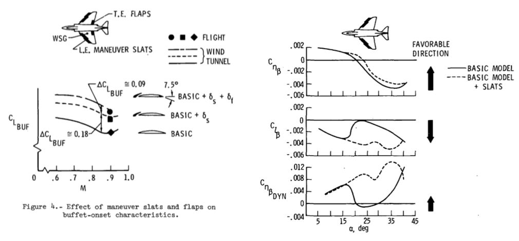
Fig. 2.48 Impact of TE and LE flap of the F-4 Phantom for its maneuverability and high AoA stability [8]

Fig. 2.49 Cnb characteristic of old jets having delta and swept wing; J-35 and AJS-37 designs using complex delta wing showed better direction stability than conventional swept wing or simple delta wings of US [1]
Tails positioned behind of the main-wing like VT and HT also affects the high AoA characteristics of the jet fighters. As described in the conventional theory, HT is swallowed by downstream of the main-wing, and generate negative lift and positive pitching moment. Recent fighters like F-22, F-35, Pak-Fa, J-31 in Fig. 2.40 positioned HT very closed to main-wing to avoid such a problem. When the HT is closed to main-wing, there is no room to face downstream for HT. Thus, HT could avoid downstream of main-wing which improve L/D characteristics of the jet fighters. Most famous example of VT design for jet fighters is F/A-18 as described in the previous contents. Vortex generated by strake, nose or main-wing is designed to pass around VT to maintain controllability in high AoA as shown in Fig. 2.50 [9].

Fig. 2.50 Position of VT relative to LE vortex [9] for F-22 model in high AoA
* Reference
[1] Karling, K., 1986, Aerodynamics of Aircraft 37 – Part 1 : General Characteristics at Low Speed, NASA TM-88403
[2] Ray, E. J., et al., 1972, Maneuver and Buffet Characteristics of Fighter Aircraft, NASA TN D-7131
[3] Henderson, W. P., 1978, Effects of Wing Leading Edge Flap Deflections on Subsonic Longitudinal Aerodynamic Characteristics of a Wing-Fuselage Configuration with a 44 deg Swept Wing, NASA Technical Paper 1351
[4] Sisk, T. R., and Matheny, N. W., 1980, Precision Controllability of the YF-17 Airplane, NASA Technical Paper 1677
[5] Monahan, R. C., and Friend, E. L., 1973, Effects of Flaps on Buffet Characteristics and Wing-Rock Onset of an F-8C Airplane at Subsonic and Transonic Speeds. NASA TM X-2873
[6] Kraus, W., 1980, Delta Canard Configuration at High Angle of Attack, ICAS80-13.1, 12th ICAS Congress
[7] Mason, W. H., Some High Alpha and Handling Qualities Aerodynamics, Configuration Aerodynamics Class
[8] Ray, E. J., et al., 1972, Maneuver and Buffet Characteristics of Fighter Aircraft, NASA TN D-7131
19730017272_LEF_wing
[9] Dean J. P., et al., High Resolution CFD Simulation of Maneuvering Aircraft Using the CREATE-AV / Kestrel Solver, AIAA 2011-1109, 49th AIAA Aerospace Science Meeting, AIAA-2011-1109
[10] Chambers, J. R., 1986, High Angle of Attack Aerodynamics: Lessons Learned, AIAA 86, AIAA 4th Applied Aerodynamics Conference
[11] Jeans, T. J., et al., 2008, Aerodynamic Analysis of a Generic Fighter with a Chine Fuselage/Delta Wing Configuration Using Delayed Detached Eddy Simulation, AIAA 2008-6228, 26th AIAA Applied Aerodynamics Conference
[12] Wooden, P. A., et al., CFD Prediction of Wing Pressure Distributions on the F-35 at Angles of Attack for Transonic Maneuvers, 25th AIAA Applied Aerodynamics Conference
Very good information of High alpha design!!!
답글삭제