Previous Work Status
- Initial Kick-Off & Design Progress
The new topic for My page : Optimization of Supersonic aerodynamic aircraftSupersonic Airliner design using Joint wing (Diamond wing) - Part 1
- Other Supersonic Jet or Innovative Design Reference
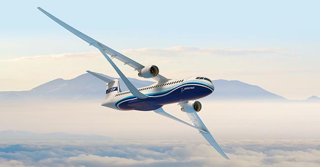
Boeing's New Truss-Braced Wing
Various SST project images
Boomsupersonic's XB-1
- Performance Evaluation via Missile / Flight-SIM
Missile-SIM : Performance Evaluation for Iskander / Kh-47M2 Kinzhal & ATACMS+Booster
Flight-SIM : Trajectory & Performance Analysis for Jet Aircraft
Flight-SIM : Initial Version of the Flight-SIM w/ Demo
Flight-SIM : Initial Version of the Flight-SIM w/ Demo II
Flight-SIM : Initial Version of the Flight-SIM w/ Demo II

2. Construction of Aerodynamic/Propulsion/Weight DB
1) Weight DB
Weight of the aircraft is estimated from the reference as shown in the Figure below. Reference roughly configured the weight of the Truss-Wing as 65% of the conventional wing. From this result, the ZFW (Zero-Fuel-Weight) is saved about 3 tons.


2) Propulsion DB
Basically I made no difference on the thrust value of the CFM-56 class engine while I assumed pressure recovery data based on the 3 shock inlet.

3) Aerodynamic DB
Geometry of the two aircraft, SupLiner Mk.1 and A320 are shown; similar size of cabin and engine are represented. Only modification of the engine is added shock-cone to gain enough pressure recovery value in the supersonic condition.
Specific estimation result for the generic A320 class airliner is shown in my previous article (Flight-SIM : Generic DB of single-aisle Airliner : Part 2).


Flight-SIM will evaluate Range and Fuel economy performance in the next article.

CFD result is supplementary provided (Mesh, iteration, case set up are very rough compare to the full-academic or industrial purpose set up due to '4-core laptop for FLUENT'; please understand about it)


M1.1 AoA 0deg - Mach Contour

M1.8 AoA 6deg - Mach Contour


M1.8 AoA 6deg - Pressure Contour