Table of Contents

Aerodynamics Series

2017년 11월 3일 금요일

Plasma Thrust Generator in Atmospheric condition


Off-topic of my Ph.D Dissertation study, I had used DBD plasma to generate thrust in sea level condition. (in 2015...)

Actually, plasma thrust generator or flow control devices are more effective at high altitude or space condition because breakdown voltage, required energy to generate plasma, become lower at these conditions. 

This short movie is simple feasibility demonstration for DBD plasma actuator, usually studied as flow control devices in low speed(Re#) condition. 

Although it requires a lot of energy to generate given thrust and generate ozone, it could be used for very small channel or re-active gas. 


More info. for my DBD plasma studies

https://www.researchgate.net/profile/Jae-San_Yoon

F-22 at ADEX 2017


Maybe, the most recent maneuver demo. of F-22

2017년 10월 27일 금요일

Scaled Composites 401

https://en.wikipedia.org/wiki/Scaled_Composites_401


Scaled Composites Model 401 is Bizzare Aircraft, made by Scale Composites. It is known as Technical Demonstrator for Unknown Customer.

It is not stealth aircraft for itself, but its many features such as V-tail, upper-engine-nacelle, complex trailing edge configuration of main wing, and style of wing-tip could be regarded as potential stealth aircraft demonstrator.

I don't have idea about what purpose of this demonstrator want to show, but stealth-long-endurance mission can be flight profile of the full-capable version of the demonstrator.

2017년 7월 22일 토요일

Su-35 Maneuver in MAKS 2017


Short Version as Summary


Longer Version

Very nice vids for Sukhoi lovers

Personally, Maneuver of Su-35 become more radical as time changes

It is very impressive

2017년 7월 21일 금요일

1. High AoA Aerodynamics for Combat Aircraft : 1.1.2

1. Why High AoA is Important for Combat Aircraft ?
1.2. Turn w/o harming speed performance using higher AoA
 As discussed in the Chap 1.1, jet-fighter go to high AoA region to achieve higher turning performance without increasing wing area (drag). As you can see in Fig. 1.16, lift coefficient is proportional to AoA while drag is square of AoA or the lift coefficient. There are three methods, increasing wing area, lift device, and expanding AoA region, for lift increment of the aircraft; each method has their own pros and cons for jet fighter application.


Fig 1.16 Lift and drag curve of typical jet fighter

Fig. 1.17 Sizing of jet fighter (W/S, T/W)

 Most simple one of the three is increasing wing area without chaning wing planform or aerofoils however, its impact on design criteria is significant than the others as shown in Fig. 1.17. Subsonic maneuverability at high alitude better did the increased wing area make while wing become prone to weight increase, loads problem at high dynamic pressure condition, and drag at high speed. Weight increase is very obvious via increment of wing area because more spars, ribs, skins, and actuators are needed. Loads problem is also clear that longer arm of the wing compel reinforced structure at the wing root to mitigate deflection of the wing. This phenomenon goes severe at low altitude with higher air density which forces higher dynamic pressure on the wing, and this is why low altitude penetrating aircraft (TSR.2 as shown in Fig. 1.18) has relatively small wing area than similar class aircrafts (Some low penetrators such as Tornado, F-111, and Su-24 choose variable swept wing to adapt complex mission profile; they should have good flight characteristics at both high and low altitude cruise).
 Contribution of the jet fighter drag is simulataneously changed at its speed and alitutude. At the high altitude and subsonic condition, aircraft faces low dynamic pressure and requires higher AoA to lift own weight (survivability from AAA, cruise efficiency of engine made jet fighter go to high altitude). However as you saw in Fig. 1.16, higher AoA generates more induced drag, and designers try to avoid that kind of situation. Low altitude or supersonic condition with higher dynamic pressure condition, everything has changed for not only structural load problem as described in the previous paragraph also for the drag. In the high dynamic pressure condition, required lift coefficient for cruise become small and contribution of the induced drag is negligible. At that time drag of the aircarft shape and area is truly important, but unfortunately, larger wing area provides more skin-friction and form drag which give negative impact on the acceleration and maximum speed performance. Indeed, increasing wing area for the lift increment is sensitive issue for the aircraft designers which cannot easily be chosen without sacrificing other performance parameters.


Fig. 1.18 TSR.2 of British; smaller wing helps this aircraft to be a better low altitude penetrator, however complex jet flap and higher AoA is required for its take-off and landing.


Fig. 1.19 Tornado, F-111, Su-24; As customers of these aircrafts requires long range (high altitude cruise with low induced drag) and low altitude penetration capability (smaller drag at higher dynamic pressure region), designers select variable swept wing to response to the complex mission profile. Usage of variable wing is now rare as low altitude intruder tactics become legacy of the past.


Fig. 1.20 Breakdown of the drag structure (Sadraey M., Aircraft Performance Analysis, 2009)


Fig. 1.21 U-2; most famous and dramatic example of the high altitude cruiser wing design. Russian M-4 and B-52 also chose high aspect ratio wing to increase cruise efficiency at the dedicated altitude. These aircraft do not have any serious consideration on acceleration and maximum speed requirement like jet fighters, and could choose large-cruise-effecient type wing.

 Adding lift devices on the wing is effective way than changing wing size in that side effect of the first method would be mitigated. This active method is similar to compromise between maximum lift and cruise or maxmimum speed condition; leading and trailing edge of the aerofoil is intentionally changed to achieve wanted lift and drag characteristics. Good reference is provided by Hoerner for the lift and drag change effect of the flap, and numerous flap devices had been developed for not only fixed wing aircraft but for cars and rotary wing aircraft (Very detailed discussions on the lift devices take large volume of talk and I recommended to read Hoerner’s work). If you have any chance to watch air-show or its video on You-Tube, you can figure out that leading edge and trailing edge devices are changed simultaneously during the maneuver of the aircraft as shown in Fig. 1.22.
LE devices helps aircraft to adjust AoA for their wings to generate maximum L/D in various AoA conditions, so, many of fighter jets choose LE flaps or slat which also delay flow separation problem at high AoA limiting maximum lift of the aircraft. In general, slat type LE devices are more effective than simple LE flap because slat type can provide fresh air on the upper surface of aerofoil which suppress flow separation, and carefully designed slat accelerates of the fresh air to increase lift. This is why the slat type is popular for airliners which requires very large lift at take-off and landing conditions; however, this type requires relatively more complex mechanism for operation than simple LE flaps. Indeed, for jet fighters, the slat type is chosen when higher lift coefficient is required (F-14 or other naval fighters) or planform is delta which is prone to flow separation and need higher lift increment via LE device.
 Compare to LE devices, TE flap is optional for the turn performance because it has clearer pros and cons than the LE ones. TE flap could generate massive lift at given AoA condition, which leads to induced drag. In the point of view for the lift, TE flap scheduling is effective way to increase lift, however, it can harm L/D performance of the fighter. So, If the jet turns with its TE flap, it can turn quickly than without it, but it loses most of its speed. This is why TE flap is optional for the turn performance enhancement as shown in Fig. 1.22. Only F/A-18 series, F-22A, and F-2A uses its TE flap during the turn while others did not. When the designers of each aircraft scheduling the flap deflection, balance between instantaneous and sustained turn affect decision of the usage of the TE flaps. As discussed in earlier, use of the TE flap could enhance the instantaneous turn performance, however, un-wanted induced drag gave negative impact on the sustained turn performance. Possible compromising method for this situation is that TE flap is deflected only when the jet certainly loses its energy. This method probably be used by the designers who should optimize their jet however, unfortunately, effectiveness of the most TE flap is gradually decreased at the high AoA region. So, the jet fighter like F-16, and Su-35 did not choose to use TE flap during the turn; designers gave more weight on sustaining energy rather than instantaneous turn.
 As a summary of the adding lift devices on the jet fighter, compare to the previous simple method, increase of the main wing area, the adding lift devices enhance the turn performance without harming speed related performance, and be loved by many aeronautical engineers who should satisfy their customers. Complex flap system could provide attractive increment of lift coefficient however this level of the system costs complexity and structural weakness. And engineers should notice that effectiveness of the flap is not guaranteed at the various flow conditions where the jet fighter should encounter.

** Additionally, F-22A deflects its aileron in the counter direction of the TE flap, and it probably related to the suppression of the wing-tip flow separation. Role of this kinds of technique will be discussed in the high AoA part.


Fig. 1.22 Various examples (F/A-18A, F/A-18F, F-22A, Su-35, F-2A, F-16, Eurofighter, Mirage 2000) of LE and TE device scheduling. F/A-18A, F/A-18F, F-22A, and F-2A uses their TE and LE flaps to maximize their turn performance while others uses only LE flaps. Details of reason is described in the text.


Fig. 1.23 Various flap types (LE and TE)

 Last method we discuss here is making jet fighter enter the high AoA. Fig. 1.16 naturally reveals aircraft can achieve higher lift at high AoA. ‘Using high AoA region for turn’ shows similar characteristics of using TE flap; it induces more lift and costs drag to lose its speed. In F-16, designers limited its max AoA due to its deep-stall characteristic, on the other hands, F-16 can maintain its speed during the turn due to the effort of this limiter. In the old days of ‘dog fighting era’, balance of the ‘sustain’ and ‘instantaneous’ capability of the F-16 deserves praise, however, advent of the modern short range missiles does not give any rooms for ‘sustain’ turn. Few quicker instantaneous turn could determine jet fighter’s fate. Maybe this kind of trend change is a reason why USAF choose F-35 as replacement of F-16 which cannot maintain higher turn rate for a long time than its predecessor. They also thought capability related to the energy can be covered by advantage of sensors and stealth, and sustaining turn capability will become legacy of the old school due to the fatality of short range missiles and future-possible-laser-turret which will neutralize any advantage of traditional fighters. Compare to the additional lift devices on the wing and increase of wing area, entering high AoA region to achieve better turning performance does not require any additional mechanical system, weight, and degradation of other performance parameters, and amount of the obtained lift is much larger than that of lift devices. Indeed, due to the effort of growth of the computational fluid dynamics (CFD) and advanced flight control system, AoA limit of jet fighter is relaxed for most 4.5th and 5th generation fighters.
 In the previous paragraph, there is no reason to hesitate using higher AoA region for turn, however, every fighter cannot enter high AoA region. Why? Aeronautical risk holds back of the aircraft to enter the high AoA. Aircraft including jet fighters have various wing surfaces with deflectable part to maintain stability in air-flow perturbation. Two directional perturbation of the aircraft are change of AoA and Side-slip angle of the flow which can drive aircraft in departure status (un-controllable status of the aircraft which should be avoided). Vertical and horizontal tails stabilize aircraft in longitudinal, directional and lateral directions, however, effectiveness of the tails is decreased as AoA is increased. Details of the high AoA aerodynamics will be discussed in Chap. 2, however, brief reasons for HARD things in the high AoA is shown in next paragraph.
 At the high AoA, aircraft fall into very-different dynamics; main reason for this change is wake from main wing and body as shown in Fig. 1.24. As AoA is increased, projected area from the aircraft is increased, and dramatic flow field change occurs such as vortex generation, vortex breakdown, flow bubble, and its separation. These kinds of non-linear aerodynamics behavior make aircraft un-predictable and dangerous. Except, aircraft having canard or similar control surfaces, horizontal and vertical tails is submerged in the downstream of this ‘non-linear’, and it results that aircraft can lose effectiveness of the tails at high AoA. If the tails lose their effectiveness, problem is not just ‘lose control’; AoA and side-slip angles can be diverged and lead to fatal spin which took lots of lives of pilots at the early time of the aviation. Although the aircraft does not fall into that kind of deadly event, problems like wing-rock or buffet still should be considered in high AoA to provide appropriate handling quality for the pilots.
As a summary of the entering high AoA, it does not require any sacrifice of other performance or additional mechanical system. Although usefulness of the method is limited for instantaneous turn, the instantaneous turn performance is emphasized in modern air-to-air combat. Only obstacle for the entering high AoA is un-predictable characteristics of flow separation which leads to fatal accident of the aircraft. However, modern control strategy and CFD help to expand AoA limit of the jet fighters without taking risky flight tests. Indeed, high AoA aerodynamics is important for achieving better fighting capability of the fighter, and I will deeply discuss about high AoA aerodynamics at the next Chap. 2.


Fig. 1.24 Wake problem via high AoA wake of main wing

2017년 4월 21일 금요일

1. High AoA Aerodynamics for Combat Aircraft : 1.1.1.B

1. Why High AoA is Important for Combat Aircraft ?
1.1. Long History of “Turn vs Speed” - One Compromise : Go to High AoA
PART B
 During the Falklands and Gulf war, missiles reclaim their position in the aerial combat via improving their reliance and range. IR seekers of the WVR missiles expanded their angular range from direct 6’o clock to all-aspect-angle of the enemy fighters while BVR missiles got own active sensors to achieve independence from the ‘shooter’ aircraft. More than that, after collapse of the Soviet Union, Off-boresight performance of the R-73 shocked Western counter-part and stimulated development of the advanced WVR missiles including ASRAAM, IRIS-T, AIM-9X, Python-4, and MICA-IR. These missiles even can track targets beyond shoulder of the pilots during combat maneuver, and has lock-on-after-launch (LOAL) capability to handle unexpected situations. 
 The first generation of the active seekers on the BVR missiles was very large and complex system like old-times 1000 lb weight AIM-54. At the late 80’s, time of AIM-120s, the size of the seeker can be fit into the size of standard medium range missiles, and radar of the fighters became free from fully-guidance-task. Combination of modern BVR and WVR missiles is now standard armament of the aircraft for aerial combat. In a long term, this trend is obvious since advent of the missiles, maybe lessons and learns from the Vietnam war just delayed it. 


Fig. 1.9 Advance of WVR missiles in their range/angle


Fig. 1.10 Change of AIM-7 and 120 via advance of electric technology

 Other Important decisive change in the picture of the aerial combat is ‘Stealth’ performance. 
 Evolution of the radar and missile did not provide good aspect on the aircraft; big SAMs for regional defense evolved as small and easily portable missiles without harming their fatality. Record of the loss of IAF during the middle east wars and interruption of the SAMs on the air missions during the Gulf war showed that radars on the air and ground platform left very small room for the fighters. F-117, one of the revolutionary aircraft in the aviation history, showed how stealth aircraft neutralized complicated air-defense system consisting of latest generation of SAMs and jet fighters. Actually, before F-117, a lot of special purposed aircrafts such as U-2 and SR-71 already considered ‘stealth’ performance as one of the important parameters however penalty of stealth performance for these early aircrafts, cost and performance degradation, make application of stealth performance impractical. After advent of F-117, considering stealth performance for the tactical aircraft became reality, and finally there was one more added consideration for performance inventory of the jet fighters. 


Fig. 1.11 Stealth fighter examples (Left: F-117, Right: F-22)

 The latest situation changes after 70’s gave fighter designers headache due to a lot of considerations. Contrary to the past fact that 40’s war-birds just chased speed, just in 40 years, designers should balance many goals to make successful jet fighter although recent fighters pursue advanced missile, stealth, and situation awareness performance rather than classical speed and maneuver performances. The important turning point of the weighting and balancing of these parameters was ATF project for USAF at late 80’s. This project was the first project for the strongest country which can chase every known goals of the list. Because lots of performance goals can be followed, contenders from many companies, Lockheed, Boeing, Northrop, McDonnell, Rockwell, Grumman, and General Dynamics, proposed many concepts emphasizing their own important performance parameters. After initial filtering out, it was obvious that USAF abandoned ‘All-in’ concept from companies, such as speed one (super-cruiser from Boeing and Rockwell), maneuverability one (X-29 style from Grumman) are out of competition. The concept aircrafts having possibility that lack of one of parameter on the list were also eliminated from competitions; it showed that US did not want to repeat their mistake of 60’s. 


Fig. 1.12 ATF initial concepts; Boeing, McDonnell, Rockwell, Grumman, and General Dynamics

 The two best contenders of the projects were YF-22 and 23, brain-child of Lockheed and Northrop respectively. The first-one, YF-22, is result of the subtle balancing of the all known parameters of the fighter design; speed, maneuverability, sensors, armament, and stealth capabilities. In order to achieve the ‘Best’ for whole areas of the performance, a lot of advanced technologies were used, thrust vectoring (TVC) with most powerful engine at that time, S-shaped duct, internal weapon bays, complicated combination and scheduling of control surfaces at high AoA, angled-body-surfaces for stealth, and active phased array radar (AESA). None of these were whole brand new technologies however combination of these for one aircraft was the first attempt for Lockheed Martin. 
 Northrop’s YF-23 was also well balanced aircraft among contenders. However compared to the Lockheed’s YF-22, they did not installed TVC on their tails while aircraft had longer-slimed and stealthier fuselage, at least it seemed. Like ATB competition held at just before ATF, Northrop’s aircraft seemed to have more potential for further growth. Although Northrop sacrificed super-maneuverability using TVC, they had wider body and wing for better maneuverability at conventional AoA region than past fighter and even F-22. Also this wider and long body and wing help strategic maneuverability, always one of the important for the US since WWII, and super-cruise capability in given thrust condition. Actually, in the past competitions in the US, most requirement for the fighter was well defined, and most contenders had similar performance even they had different geometry. However, in the ATF, companies arbitrary pursued their own goals in different geometry, and it seemed fight among concepts which one is the most appropriate for the future aerial combat. 


Fig. 1.13 YF-22 and YF-23

 Still, there are many argues about choice of USAF; someone insists YF-23 is better for the tommorow’s environment. Anyway USAF chose YF-22 as F-22 for the USAF inventory, and which decide fate of two companies and affect other adversary countries of the US. This decision showed USAF did not want any lack-of-performance for one possible parameter, maybe except cost. It looked conservative, and still nightmare of Vietnam war alive. Except F-35, designed mainly for general-day-one attacker, most recent fighters of other countries, Pak-FA, J-20, X-3 of Japan, KF-X, Rafale, Eurofighter should care about the whole parameters which they can completely care or not. 
 6th generation fighter, F/A-XX for USN, is still ambitious about their concepts like initial phase of the ATF; directed energy weapon (DEW) might be added as a new member of performance inventory. If DEW is attached at the aircraft, aircraft become heavier to support massive power requirement of laser, and do not need to have good maneuverability due to its unlimited bullet speed, deep-magazine and fast-tracking gymbal of the turret. If future air-warfare goes in that way, fighters will follows fate of ship-of-the-line, and UCAV or similar one substitute current fighter’s position in the aerial combat. Speculation of the future aerial combat is very interesting one for me, however it is not focus of current article and nothing is certain at 2017. Further discussion for the future air combat will be discussed at Chap. 4 of this. Before DEW is matured for small-sized UCAV which possibly neutralize advantages of maneuverability of the aircraft, balancing of the fighter-design-parameters is important task for the current age fighters and the future-substitute of the ship-of-the-line. 


Fig 1.14 Concept art of 6th generation fighter and DEW

 It has been a long story that these parameters are important for the fighter design. Situation-awareness payloads, speed, acceleration, stealthy exterior design, and maneuverability should compromise each other to make ‘appropriate balance’ for the good fighter. When the aircraft is sized for their mission, thrust and weight including fuel and situation awareness are decided to meet its purposes. After thrust and rough size of the aircraft is decided, balancing of the speed, acceleration and turning performance is the issue. It is nature law of the aerodynamics that higher lift for the turning performance induces drag, proportional to the square of the lift. So, many engineers have found ways to achieve higher lift in the given drag penalty; RSS, relaxed static stability, flap scheduling, and expanding AoA capability of the aircraft were proposed to obtain this goal. The RSS with fly-by-wire system, common solution for the fighter since F-16, could enhance lift via reducing trim drag and a good solution for the sustained turn and cruise efficiency. Flap scheduling for the leading and trailing edge of the wing could modify the camber of the airfoils to obtain higher lift coefficient. These two solution is good solution for the given AoA, however the effect of two subtle solutions are limited in the point of view for the total lift. 
 The expanding AoA region is more radical solution for the jet fighter especially for instantaneous turn which become important as lethality of the missile is increased and one or two chances are only available for the fighters. Indeed, in order to ‘truly’ enhance the combat effectiveness of the jet fighter without harming speed relative performances, jet fighter should enter the higher AoA region to shoot their missiles or evade attack of the enemy aircraft. 


Fig 1.15 High AoA turn of the jet fighter

In the next 1.1.2, I’ll discuss about high AoA of jet fighter more specifically. 

2017년 4월 1일 토요일

1. High AoA Aerodynamics for Combat Aircraft : 1.1.1.A

1. Why High AoA is Important for Combat Aircraft ?
1.1. Long History of “Turn vs Speed” - One Compromise : Go to High AoA
 PART A
 “Speed is life”, maybe the most famous rule for the fighter aircraft, and this rule shows its influence from WWI to modern air warfare. Advantage of the speed gives pilots initiative of the engagement among ‘leave’, ‘engage’, ‘pursuit’ and maybe other choices. The advantage could divide result of engagement result as live or death, and accumulation of exchange ratio is critical even for strategic level. One of the dramatic example of ‘speed-dominance’ is American and German-war-bird in WWII. Those two-country-made aircraft such as Bf 109, Fw 190, P-38, P-47, F6F, F4U, and P-51 used energy-fighting tactics to fight against other-country-made fighters effectively, and they are famous for their performance during the war.


Fig. 1.1. Top: Fw 190 uses vertical tactics based on energy advantage, typical style of Fw 190 

Bottom : Energy advantage of aircraft is not only useful for initiative of the engagement, but for chasing enemy’s 6’o clock


Fig. 1.2. Top: F6F of USN and A6M is good example of showing “speed is life”, about 30~50km/h difference of maximum speed determine their destiny

Bottom : Extreme long range and top class maximum speed made P-51 as ultimate fighter

 This prerequisite was based on the ‘gun-weaponry’ of the classic air-warfare of which weapon has limited range and angle to shoot against enemy aircraft. Most people easily thought that this limited range and angle of the gun-weaponry change dog-fight into turn-dominant-stage, however the limited effective range of the gun system help speed-advantage aircraft to win easily. For example, the most advanced gun on board cannot achieve kill beyond for more than 2 nm except stationary targets, and the safe-distance is easily obtained by energy-tactics fighters. Turn-based fighters without having enough speed to catch up energy-tactics fighters can only aim their guns on one energy-tactics fighters while the other energy-tactics fighters can pursuit and shoot easily the turn-based fighters. Most of the aerial combat has been form of ‘many-versus-many’ and this is why energy-tactics could dominate gun-weaponry air-warfare.

 (If you have more interest about turn-vs-energy tactics, lots of other papers or articles were already written and discussed about this topic.)

 Dominance of the speed-priority was peaked at just before start of the Vietnam war, however reason for the emphasis on the speed became different after WWII. At the time of end of the WWII and start of the Cold-war age, advent of early form of the missile and fear from the high-speed nuclear bombers changed air-warfare permanently. For a while, most fighters became interceptor to block the bombers rather than pure fighter role, which means that fighters carried more missiles with higher maximum speed. Due to the limited performance of the early jet engines and radars (for missile guidance), aircraft should have big-slender body to reduce drag and carry big electronics. This kinds of evolution naturally aggravated “maneuverability” of the fighters in fighters-to-fighters


Fig. 1.3. Top speed of 50~60’s jets, F-86, F-100, and MiG-21 can be shown, and their trend is remarkable (Design for Air Combat, R Whitford)

 While the fighters became bomber-interceptors, acceleration and minimum turning performance of the fighter were sacrificed for their primary target performances. Doctrines for ‘long-range-penetrating-fighters for tactical nuclear strike’ and ‘missile-replacing-dog-fighting’ made situation even worse, and fighters like F-105, F-111 (long-range-penetrating), and F-4 (missile-replacing-dog-fighting) had been produced to meet these needs. Only few light fighters at that age kept reasonable maneuverability not because of opposite ideas but for other reasons such as keeping reasonable prices (F-5 series), and point intercepting performance (Mirage III family and MiG-17/19).


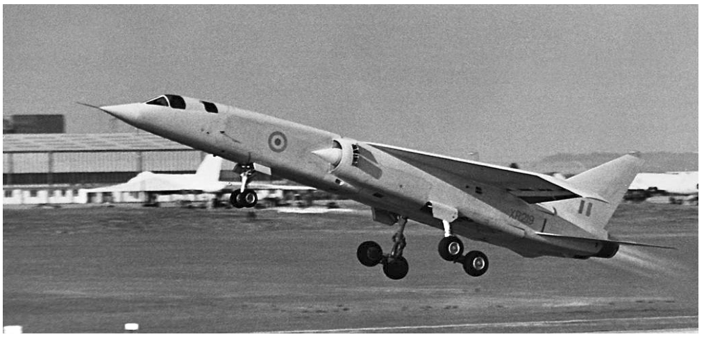
Fig. 1.4. One of the famous and typical example of long-range-penetrating-fighters for tactical nuclear strike; suffering lack of air-to-air capability

 Dictatorship of the speed and missiles went to end because of many reasons at end of 60’s
(1) Vietnam war proved WVR dog fighting still occurs (missiles cannot do everything)
(2) Fear of high-speed nuclear bombers changed to fear of SLBM/ICBM
(3) Growth of jet engines and electronics makes room for fighter design

 Lessons and Learned from (1) is very famous for aviation history, and I do not need to repeat about this. Reason (2) is not famous as (1) but important, because fighters were free from ‘strategic-intercepting-work’. While small air-to-air missiles proved its immature performance in theater of south-east Asia, big missiles for strategic nuclear strike widen its proportion in ‘Global-Level’ weapon inventory. Advent of surface to air missile, SAM, also instigated fall of high-speed nuclear bombers from crown of the strategic strike mission. This is the reason why XB-70, B-1A, T-4 is cancelled, and high rank officers in the air-forces threw their sole-purpose-bomber-interceptors like old shoe. Only aircraft like Tornado ADV, F-14, and MiG-25/31 survived in UK, US, and Russia as dedicated interceptor where intercept mission is still important (UK strongly emphasized intercepting performance on Eurofighter replacing Tornado ADV even at the current age).
 At the early stage of the Cold war, as I mentioned earlier, integration of big radar and powerful jet engine itself was a big task for fighter designers, and most of the volume and system should be satisfied to support the two big items. Reason (3) changed situation dramatically. Radar of 70’s which can detect enemy from few tens of nm and guide missiles weighted much less and were more powerful than that of 60’s. Increase of engine thrust in given volume helped to reduce fuel volume in the jet aircraft, and even more, advent of the turbo-fan engine improved fuel-economy of the fighter to reasonable level.


Fig. 1.5. Owing to advance of electronic technology, capability of the radar is increased without penalty of weight (trend of weight is not shown) (Fundamental of Fighter Design, R Whitford)


Fig. 1.6. Increase of pressure ratio, specific thrust, and T/W of jet engines (Fundamental of Fighter Design, R Whitford)

 Owing to the situation changes and technology advances, fighters changed their enemy from bombers and ground target to ‘other fighters’. As proved in the Vietnam war, fighting in the supersonic region for more than Mach 1.4 is ‘unlikely-happen’ between fighters due to its limited size of fuel tank and external stores. At the age of interceptors, from 50 to 60’s, because jet fighters already expanded their maximum speed from subsonic to Mach 2, the designers looked forward for more practical performance parameters such as acceleration, turning performance, rate of climbs, and etc, called “maneuverability”. 
 American teen series, F-14/15/16/18, and Soviet originated MiG-29 and Su-27 were born in this trend of post-Vietnam war, and still enjoyed their heydays (although part of reason came from end of the Cold war). Post-Vietnam war jet fighters were result of delicate balancing among speed, acceleration, and turning performances; T/W, W/S of the jet were carefully selected to meet their complex requirements and to overcome possible adversary in the sky.


Fig. 1.7. T/W, W/S of various jet fighters, noticeable change of trend after 70’s jets (Design for Air Combat, R Whitford)


Fig. 1.8. Turning capability comparison of F-16 (70’s) and F-4 (60's)

Continue-in Part. B