This is a new proposed concept that minimizing launch cost, expendable part
1. Air-Launch for free launch angle, adding kinematic energy,
2. Recovery 1st Stage Part - which lands sea-surface smoothly - validated later
3. 2nd/3rd Stage 1-time-use
Concept Art, 1st stage art is borrowed from Russian Baikal Booster, however this booster is not engine propelled, using expanded glide wing only.
Becuase mother aircraft is limited to small-transport, MTOW is less than 25t with 300kg payload. Target altitude is 600km with 7.9km/s. Weight of empty structure is assumed as 20% of propellant mass.
Initial sizing is 600km with 7.5km/s with specific mass distribution. Engine ISP is assumed as typical liquid propelled engine.
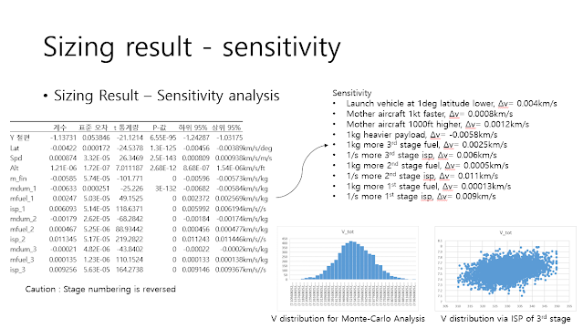
Sensitivity result for mass distribution change.
In order to keep same total velocity, rocket need additional 5.7t for 1st stage.
30t rocket from air could reach powerful LEO condition.
30.4t rocket could increase payload from 300 to 405kg.
Air-Launch condition added 0.12km/s for Rocket at 24deg Latitude.
If 1st stage is changed to solid motor, because of low ISP, rocket should be increased to 28.7t
Gliding Analysis for Wing-Extended configuration; OpenVSP is used
L/D is not optimized yet but tested
Although, L/D is not fully optimized it land <300ft/min at M0.3 Speed.
SUMMARY
Concept study for Flyback-Booster
20t class rocket with 300kg payload is feasible; land-launch requires additional weight.
- 0.12km/s is added by aircraft condition.
Landing condition is reviewed and it shows glide-wing made <300ft/min landing at M0.3.
Due to the instability, I tried to make controller for Longitudinal and Lateral direction. There is no proper design for Observer; it is just for possibility check for control surfaces.
We could figure out that aircraft is very-unstable for lateral direction as we discussed; however proper controller could mitigate the problem.
This is a kind of reverse engineering contents for MQ-25 which I have interest for its beginning. Still there is no exact data for this aircraft, so I should imagine or estimate some part of design. It does lead to in-exact prediction, but I hope it can provide some provision.
Progress are shown in below
1. Shape Design and Sizing for Initial Estimation
2. Aerodynamic Characteristics
3. Stability and Control Characteristics
4. Performance (Flight Trajectory) Analysis
1. Shape Design and Sizing for Initial Estimation
Roughly designed MQ-25 style model is shown; Planform of main-wing and v-tail is from 3-view while airfoil is approximated as 0.1c thickness with CL 0.2. Canted angle is 70deg from vertical plane.
Based on geometric design, rough sizing is done. Empty weight, baseline fuel, and cruise condition are configured to fit known data. Breguet Range equation shows that it is similar to the mission profile; delivering 17,000lb for 500nm distance.
Result is 502nm with 3,750lb fuel; it means that the modeled MQ-25 is very efficient for aerial refueling compared to F/A-18E/F. Heavier F/A-18E/F carrying much more fuel than MQ-25 for the same mission.
2. Aerodynamic Characteristics
Baseline model carrying pair of pod depicting A/A42R-1 pod contributed to drag. CG is assumed to 7.1m from the Nose (Total length of aircraft is 17m). Control surfaces are v-tail, inboard and outboard of main wing.
At Cruise condition (M0.6), OpenVSP provides 6DOF aerodynamic coefficients. L/D is from 12 to 17 at AoA 0~2deg.
M0.2 w/ 30deg flap is powered approach condition; flap is deflection of in and outboard conforl surfaces which are shown in several pictures. it decreaes max L/D due to excessive drag but good at AoA 0 deg.
3. Stability and Control Characteristics
OpenVSP provides full 6DOF coefficients and inserted these to longitudinal & lateral matrix to get SnC characteristics. Inertia of model is harder than predicting pure-aero; inertia value is assumed as 1/8 of small transport aircraft.
It results that 1.5min period of Phugoid w/ 4min of 1/e attenuation. Important thing happened at lateral motion. As shown in coefficient result, it did not have directional stability which requires active damper for real application.
4. Performance (Flight Trajectory) Analysis
Engine is modeled by parametric ideal engine; fortunately Rolls Royce AE 3007 engine has well known data. Thrust and Fuel-Flow table is generated for flight condition while thrust is degraded for 5% to account inlet/exhaust shape.
Trajectory of 1st mission shows modeled aircraft deliver up to 17,000lb fuel for 500nm distance using 3,750lb own fuel. M0.6 at 25,000ft cruise condition is assumed while 17,000lb fule is gone at 500nm. CL conditino change shows that aircraft flew designed condition and CD is about 0.02.
Max-ferry mission is calculated; if external fuel can be used for MQ-25 entirely, it can fly almost 7000nm for 22hr. There is a doubt about its performance.
There are several cases; detailed discussion will be shown.
Result for several mission expected for MQ-25; specification is fitted to reference mission.
MQ-25 can reach 6930nm if it can use whole fuel for own flight; 19,730lb is used.
Light-patrol mission carrying two 500lb shows 509nm with standard internal fuel.
If MQ-25 goes 35kft to save fuel, it can extend its range for 70nm.